Nikon’s Large-Envelope X-Ray CT System Installed in Hyundai Motor North America’s New Safety, Investigation Laboratory

 Nikon Metrology, Inc, and Hyundai Motor North America announced that Hyundai has purchased and installed Nikon’s X-ray computed tomography (CT) system. This represents a significant investment in the success of Hyundai’s newly opened $51.4 million Safety Test and Investigation Laboratory (STIL) in Superior Township, MI.
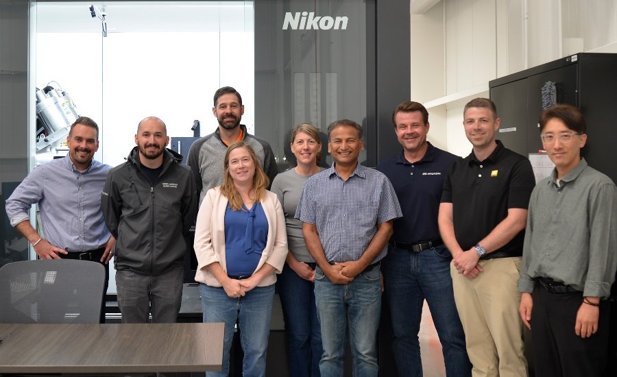
Nikon’s X-ray CT system offers a large scanning volume, multi-source flexibility, dual-detector functionality, and an extensive range of enhancements which together provides users of the system with truly exceptional inspection capabilities.

Hyundai Motor North America utilizes Nikon’s X-ray CT system in their STIL facility for important analytic processes, including nondestructive inspection of components such as air bag inflators, lock mechanisms, seat switches, struts, impellers, and additive parts.

“Having the on-site capabilities to view the inner structures and components of materials and mechanisms through the advanced Nikon X-ray CT system provides Hyundai with detailed datapoints that would otherwise take weeks to evaluate,” says Ben Michajlyszyn, director, Safety Test and Investigation Laboratory, Hyundai Motor North America.

The successful collaboration between Nikon Metrology and Hyundai Motor North America is the direct result of their mutual commitment to world-class engineering and manufacturing. 

Nikon’s X-ray CT systems have been built to handle the most demanding inspection tasks in the manufacturing world, both now and in the years to come.  “The multi-tube, multi-detector configuration delivers a highly flexible system capable of producing top-quality results on small, low-density components such as impellers as well as on larger, multi-material assemblies such as airbag inflators. This flexibility to do more on a single system can yield a greater ROI and the ability to adapt to Hyundai’s needs as their business and inspection requirements advance,” says Chris Peitsch, Global Sales Manager, Nikon Metrology. 

Hyundai, in turn, utilizes the X-ray CT system to ensure the quality, safety, and functionality of the components that make their way into Hyundai’s award-winning automobiles. Measurement is fast, efficient, and accurate, and the nondestructive nature of the inspection is critical. Using destructive techniques on charged devices such as airbag inflators would represent potential hazards for inspectors on site at the STIL, whose mission is to increase safety for Hyundai customers and employees alike. Nikon’s X-ray CT systems are an important part of that effort, and it is representative of the valued, ongoing partnership between Hyundai and Nikon.

For more information, visit www.industry.nikon.com or www.hyundaiusa.com/.

Calypso - Point Recall with LOOP


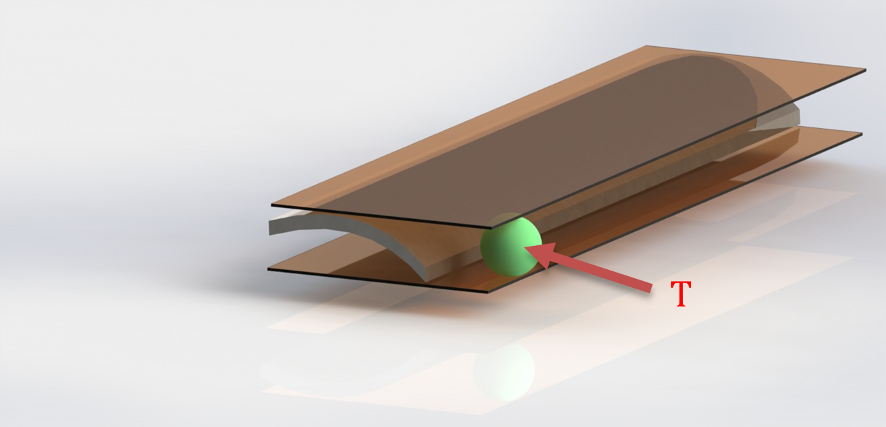
This will create a wall thickness 360° around the part top and bottom 8 points each.

To read the article click this link.

https://cmm-quarterly.squarespace.com/articles/calypso-point-recall-with-loop

Flatness - GD&T and Calypso Rev 3 Book

 Flatness - GD&T and Calypso Rev 3 Book — CMM QUARTERLY (squarespace.com)

This is an excerpt from the GD&T and Calypso Rev 3 Book

Flatness is a form tolerance that on the surface seems easy on a CMM. Simply scan the surface or place a series of points on the planar surface, and report out the variation, but we must understand the data and what results we are given.

Flatness (form tolerance): the tolerance zone is limited by two parallel planes a distance t apart.

Implies: Straightness of the surface or Straightness of the derived median line

On a surface plate layout, the surface must be isolated. The surface is checked to itself and therefore you can’t lay a part of the surface plate and scan the top surface. This would be parallelism. On the CMM this is acceptable since Calypso will calculate flatness based on the surface data regardless of the alignment or orientation.

In the flatness characteristic the plane is automatically changed to Minimum Feature, regardless of the Evaluation Setting. It is the Calypso default setting. This setting is seen in the selection dialog box when picking the feature in the Flatness dialog box.

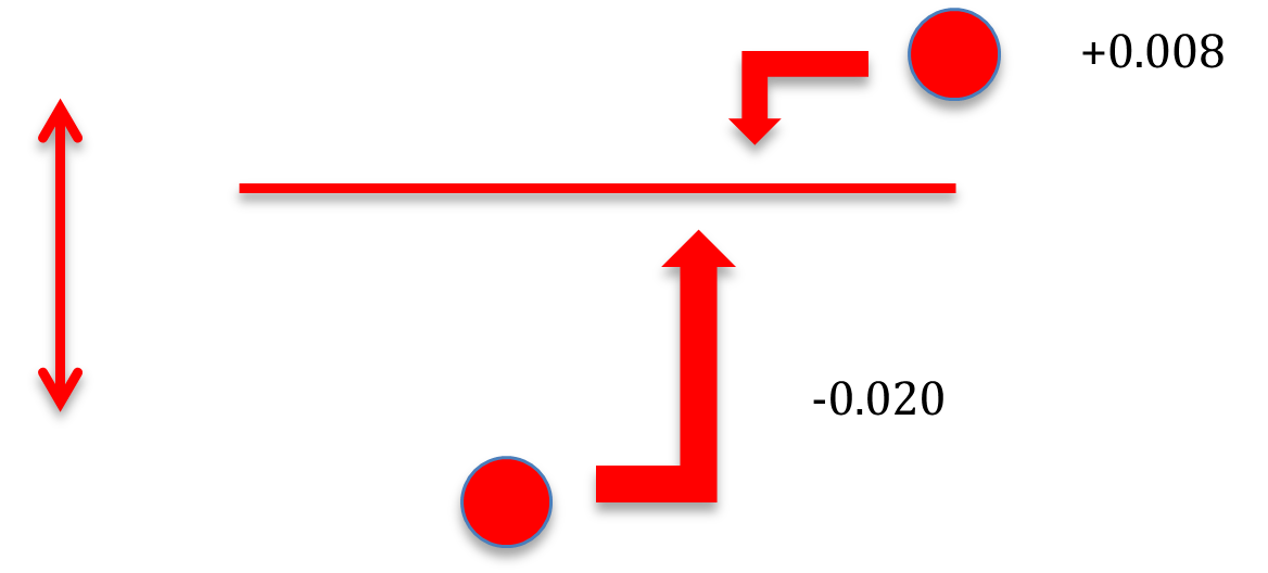
 The minimum zone creates a plane through the equally displaced points created by the highest point and the lowest points of the scan. Thus, the flatness graph will display the same min/max values.

 The plane is moved up or down to create a plane that is equally displaced between the measured points.

Measured Plane

Minimum Feature Plane

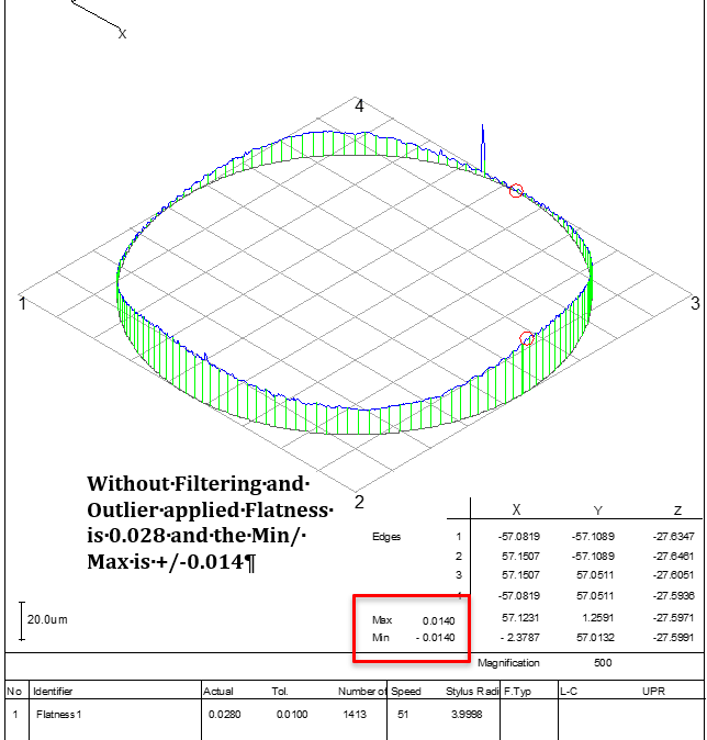
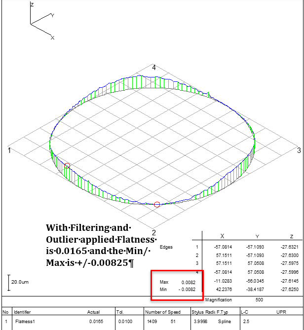
As you can see that minimum zone, or minimum feature is susceptible to outliers. One outlier could change the flatness result drastically. It is recommended that outliers and filters be applied. As stated, before it is best to set filtering and outliers defaults using Resources/ Save Load Default.


NOTE: The flatness reported in the characteristic is different than the form value reported in the feature dialog box; this is due to the LSQ calculation of the feature itself.

The current CMM Quarterly training programs on Teachable.
Calypso Basic Training 1, 2, & 3
Calypso CAD Model Training
GD&T and Calypso
CMM Manager DCC Training 1, 2, & 3
All training come with downloadable videos and pdfs. Train at your own pace.


Using the Virtual Probe Method


When calibrating a stylus tip in Calypso software it is recommended that you use Dynamic Tensor calibration at least in the initial calibration. This allows Calypso to gather the “bend data” of each individual stylus. Tensor or Geometric calibration may be used for recalibration purposes.


When using Dynamic Tensor calibration is not uncommon to receive this type of error.


This error requires you to rotate the reference sphere so that Calypso can access an unobstructed path around the reference sphere. To resolve this you may have reloaded the master probe and re-reference the sphere location. Then reloaded the stylus system and went through the entire calibration process.


Next time, try this procedure.


Creating a Set of Virtual Reference Spheres


Within the Stylus System Qualification dialog box click on the Reference Sphere Management icon.


This will open the Reference Sphere Management dialog. It is here that you will create the Virtual Reference Sphere positions. You may create as many positions as you would like. Below in Table 1 are listed the most used positions and these rotations might be a good start.


Above is your default Reference Sphere position screen. We will now add the Virtual Reference Sphere positions. To begin, click on the Copy as Virtual Reference Sphere button. This will bring up this next prompt.


Calypso will automatically select the next number for the reference sphere. Leave the number as is and click ok.

 
Now another reference sphere is added.


Change the Rotation Angle, in this case to 135 degrees, and Click Apply.


Let’s add another position. Click back on number 1 in the list and repeat the steps. Click on the Copy as Virtual Reference Sphere button. Name this one #3 and click ok. Highlight #3 in the list and change the rotation angle to 225.00 degrees and click Apply.


Repeat the steps until all of the positions are created.

Note: Inclination will be 135 on all examples
Ref Sphere Position           Rotation

1                                           45 
2                                          135
3                                          225
4                                          315
5                                          0
6                                          90
7                                          180
8                                          270


Remember all these steps where done to circumvent this error during calibration. Once you have completed the above steps it is not necessary to do them again. They will be stored for future use.


Using a Virtual Reference Sphere Position during calibration
The stylus will do a tensor calibration before this error appears.
Once this error has occurred change the Mode to Dyn. Tensor Re-qualification Mode.


Rotate the Master Sphere on the CMM table to the desired position that will allow for a dynamic calibration. It is important to just rotate around the existing position on the table. Do move it to some other location just rotate it around where it is currently located.


Open the Reference Sphere Management dialog


Now select the corresponding Virtual Reference Sphere that matches the new position on the table


Click Activate. This will now make, in this example, #3 active


You can now see that the Reference Sphere is Sphere #3


Now click on the Qualify Stylus button.


You are prompted to move the stylus and touch the stylus in the direction of the shaft.

 
This will now begin the dynamic tensor calibration. This is the scanning of the master ball since the tensor calibration portion was already completed prior to the error


The calibration is complete. Notice the Dynamic Qualification check mark is present and the Mode has changed back to Dynamic Tensor.


NOTE: By using the virtual sphere procedure, you first measure all styli in one position of the reference sphere and only then rotate the sphere to carry out the dynamic stylus qualification. Otherwise, you would have to re-qualify the sphere each time again.


PiWeb Reporting


Zeiss has added a new report feature that is fantastic. Calypso 6.0 now has the ability to expanding your reporting options. We will cover these options. Please note that PiWeb Reporting is only part of a larger optional reporting package PiWeb Reporting Plus.


PiWeb Reporting and Multiple Printout


After creating your CMM program you may want to add an additional report format. For example, you may currently have a company report format that contains your specific input parameters but in addition to that you may want to have a report that has the plots embedded within the report and a compressed format.


We will show you how to do that within this article.

PiWeb Reporting – Standard Format

Click on the link below to go to CMM Quarterly


How to setup the Standard Format Report in PiWeb Reporting


Free CMM Training

Join us at Mark Boucher Consulting, A CMM Quarterly company, forum


It's free to join


Click here to Register


The American National Standards Institute (ANSI) Approves New Quality Information Framework (QIF) v 2.0 Standard


New QIF™ V2.0 Standard:  A Major Breakthrough for Manufacturing Quality
Provides Complete & Accurate MBD along with many other enhancements for the Metrology Industry


Burleson, Texas, USA November 23, 2014 — The (DMSC, Inc.) Dimensional Metrology Standards Consortium announced today the American National Standards Institute (ANSI) has approved QIF v 2.0 (Quality Information Framework, version 2.0) as an American National Standard.  This new standard enhances the previous ANSI Standard, QIF V1.0 containing quality planning and measurement results, by providing a complete and accurate 3D product definition with semantic geometric and dimensional tolerances, definitions for measurement resources, template for measurement rules, and statistical functionality.  All of this to satisfy the digital interoperability needs for a wide variety of use cases including feature-based dimensional metrology, quality measurement planning, first article inspection, and discrete quality measurement.

On December 19th, 2013, The ANSI Board of Standards Review (BSR) approved QIF v1.0 as an American National Standard. This new standard provides, quality measurement planning (QIF Plans), first article inspection (QIF Results), and discrete quality measurement.  

QIF v2.0 resolves model-based metrologies primary “pain point,” which is obtaining a complete and accurate 3D product definition with semantic geometric and dimensional tolerances (QIF MBD). It provides cost effective XML exchange of product definition with various conformance levels of semantic PMI (e.g., GD&T) that satisfies many CAD to model-based metrology use cases.  QIF v2.0 also provides a way to define and apply measurement resources (QIF Resources), measurement rules (QIF Rules), and statistics (QIF Statistics) towards generating and communicating feature-based measurement plans based upon a plant, department, or supplier’s measurement resources and rules defined by a company and/or by part type.  QIF models include quality characteristics and measurement features as defined in the ASME Y14.5 specification and the Dimensional Measuring Interface Standard (DMIS).

ANSI approval of QIF v2.0 indicates that QIF has attained a consensus approval from a large number of subject matter experts in the digital metrology industry.  (See “About DMSC” below.) The QIF standard was designed to meet the highest industry requirements and to satisfy technological gaps that have traditionally cost industry hundreds of millions of dollars annually. The DMSC has met, and continues to meet the need for urgently required national standards in quality measurement in a timely fashion.   ANSI’s accredited Standards Developing Organizations (SDOs) operate in accordance with national and often international guidelines, and have been verified by government and peer review assessments. 
To find more information about the QIF standards please visit the QIF website at www.qifstandards.org.  To obtain your no-cost copy of the standard please send a request via email to bsquier@dmis.org.

"I am proud of our standards community and the work that we have accomplished with this new standard. This doesn’t replace DMIS (Dimensional Measurement Interface Standard) but it compliments and can harmonize with it. This new standard infrastructure is expandable to include every aspect of the Quality Information Framework, thus the name. Once adopted by the software vendors, this will allow us to properly use digital models with all the engineering requirements and quickly produce inspection and measurement plans throughout our supply chain (micro and macro), conduct inspections and measurements, then analyze and report in standard formats via AS9102 or PPAP files. This will be a huge savings throughout every manufacturing industry in our environment without any cost to the software vendor or user." said Ray Admire, DMSC Treasurer and Chairman of the Quality Measurement Standards Committee."

Manufacturing quality digital information incompatibilities are costly and affects everyone: vendors, suppliers, users, and customers.  And the digital metrology community has lacked an enterprise-wide standards solutions, UNTIL NOW, QIFv2.0, a superior standards-based digital interoperability has been ANSI approved.  Furthermore the QIF enables Manufacturing Quality to join the Model-Based Enterprise next generation of doing business.” said DMSC President Curtis Brown.


About DMSC
The Dimensional Metrology Standards Consortium (DMSC, Inc.), is an ANSI Accredited Standards Developing Organization, as well as an A-Liaison to ISO TC 184/SC1.  QIF has been developed and demonstrated with support from: Applied Automation Technologies, Boeing, Capvidia, DISCUS, Hexagon Metrology, Honeywell FM&T, InfinityQS, Innovalia Metrology , Inspec Software Corporation, IPI Solutions, John Deere, Kotem, Lockheed Martin, Metrology Integrators, Metrosage, Mitutoyo America, National Institute of Standards and Technology (NIST), Nikon Metrology, Origin International, PAS Technology, Pratt Whitney, PTC Solutions, Quality Vision International, Renishaw, Rolls Royce, Siemens PLM Software, Systems Insights, and Zeiss. 

These are many of the same experts who continue to maintain the Dimensional Measuring Interface Standard (DMIS).


QIF is a registered trademark of the DMSC.   © 2014 Dimensional Metrology Standards Consortium